Intubation Shield
Updated 04.12.20 at 16:50 PST
We are partnering with AerosolBlock.org to make acrylic intubation boxes.
Many patients infected with COVID-19 develop respiratory failure and require endotracheal intubation. Healthcare providers are at high risk of contracting COVID-19 during this process by coming in contact with droplets and aerosol from the patient. With the shortage of protective gear, a lot of providers aren’t able to wear adequate protection while intubating. To protect health care providers, Dr. Hsien Yung Lai, an anesthesiologist from Mennonite Christian Hospital in Hua Lian, Taiwan, has designed the Aerosol Box.
This acrylic box provides a barrier between the healthcare provider and the patient while still allowing freedom of movement. AerosolBlock.org matches fabricators with healthcare facilities in need of this product.
Local maker Jon Lenoff spearheaded our first Aerosol Box, and it was picked up for use at a local hospital on March 29. Below, read about how we made Version 1, what we learned, and how we modified the plan for Version 2. You’ll find that we don’t go into too much detail in some sections as there are likely better ways to do it!
VERSION 1
Supplies
- 0.116″ thick acrylic (72″ x 36″ sheet)
- acrylic cement
- 100% silicone caulking
- laser cutter
- clamps
- 2×4″ scraps of wood (to aid with clamping)
Production
We were approached to create a variant of the now widely circulated Aerosol Box with some additional side access ports and modified dimensions. An initial drawing of the adjustments was provided (Image 1).
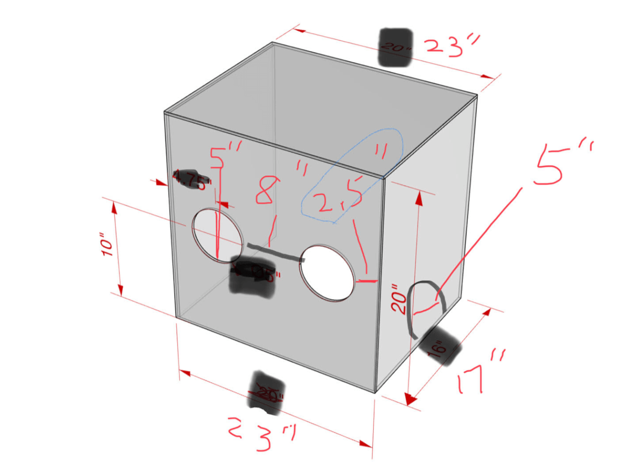
Image 1 – Drawing of requested box
We put that sketch into CAD to get clean dimensioning and to get a sense of what the box would look like once completed (Image 2).
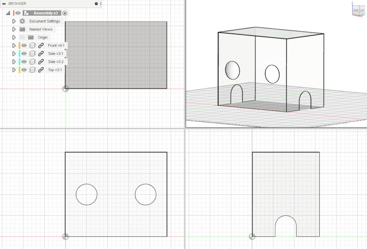
Image 2 – CAD drawing of requested box
Without requirements on material selection, thickness, or joining methods, we decided to use what was quickest, cheapest and most widely available for others to use as well. We knew the material needed to be clear, rigid, and able to be sanitized. We chose acrylic for its ease of laser cutting and its secure joining method with acrylic cement. We went through an iterative process, considering material availability, optimizing material use, and designing via CAD. We tried several layout iterations to check how much material we’d need and how we could optimize material use and minimize waste (Image 3).
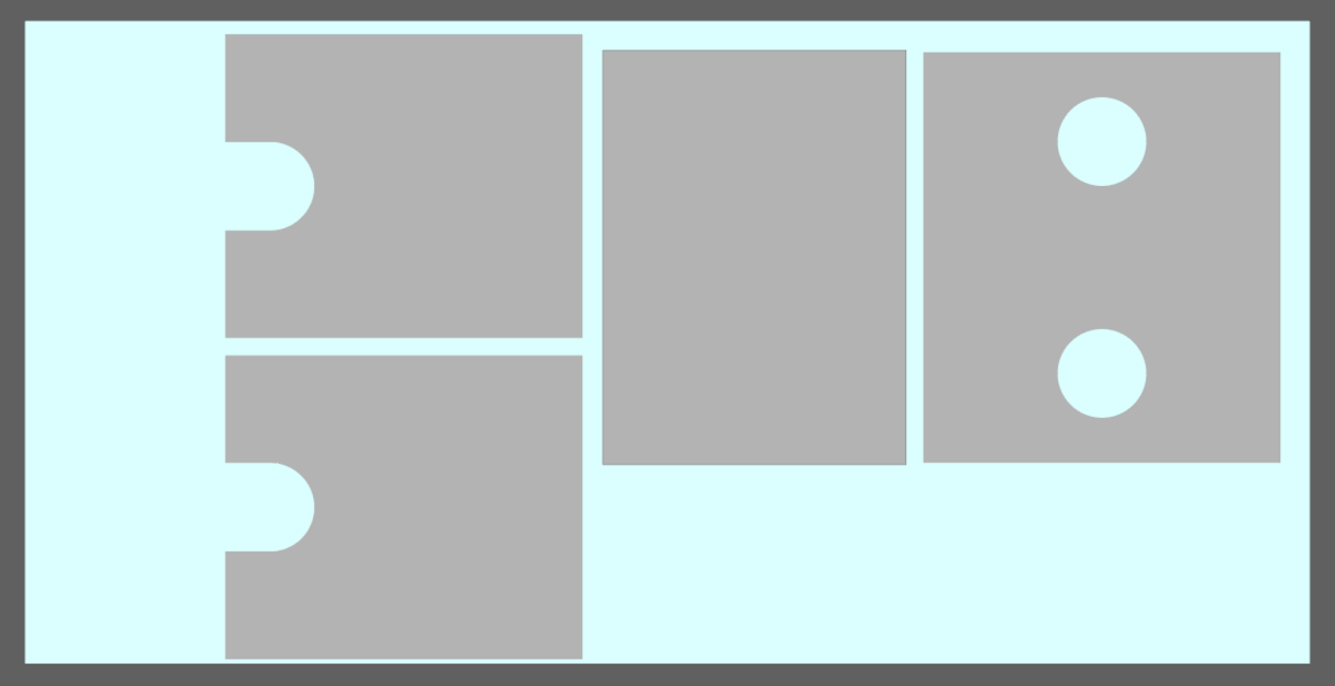
Image 3 – One of the layout iterations to check how much acrylic material we’d need and how to lay out the pieces most effectively.
We also wanted a material that could be easily sourced, and decided to use Home Depot’s stock. We chose a 72” x 36” x 0.22” sheet of acrylic that was in stock, and after tripled checking the design files, we set off for Home Depot. Upon arriving, we found they were completely sold out, so we made snap decision to go with a 72” x 36” x 0.118” sheet of acrylic instead.
With thinner material, there’s less surface area for the acrylic cement to set and for the pieces to join. This might result in small gaps that let air through as well as cause less secure joints. We planned to remedy this by caulking all the seams with a 100% silicone caulk meant for plastic sheeting. With the caulk, we’d practically be guaranteed an air-tight seal to keep everyone safe, plus we’d get additional joining strength between the sheets.
Back at the makerspace, we modified the cut files for the reduced material thickness as we wanted the material to fully cover all seams with no overhang. Once the files were done, we loaded up the sheet into the laser cutter. We removed the protective sheeting from one side of the acrylic completely and from both sides of the area that was to be cut. These protective sheets help keep the acrylic scratch free but they can contain PVC, a chemical that degrades into chlorine gas when laser cut – bad for people and machine parts.
Because the acrylic extended beyond the laser cutter bed, we built a make-shift platform out of some plastic buckets and some wood (Image 4). We positioned the far end of acrylic (away from the laser cutter) slightly higher than the portion in the laser cutter to ensure a firm and uniform pressure across the full laser bed.
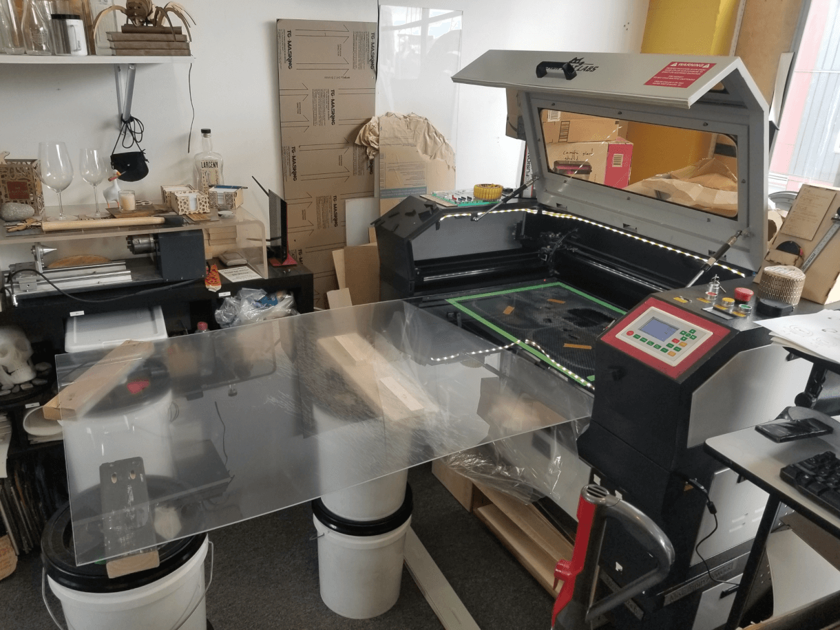
Image 4 – Positioning the acrylic sheet in the laser bed.
Cutting was straightforward and everything worked correctly the first time, which was lucky as we only had enough material for one go at it. This is why we measured 35 times and only cut once! As we cut the pieces we examined them to ensure all was well (Image 5).
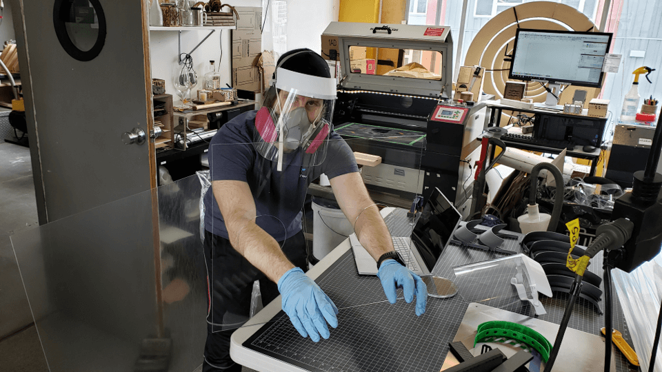
Image 5 – Acrylic after being cut.
Once everything was cut, we cleaned all the edges that would be cemented, and we built a simple jig on an outdoor table to aid in assembly. We worked outside to provide enough ventilation for the acrylic cement. We were careful to use a rigid, flat, and non-plastic surface to assemble the box and make sure everything was square. Our work surface of choice? Metal dry-erase boards (Image 6).
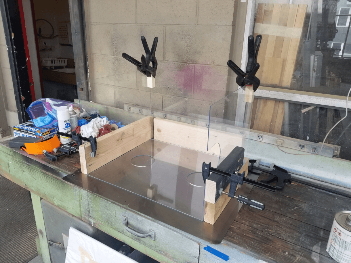
Image 6 – Assembling the box on a a rigid metal surface.
We carefully glued all the seams with acrylic cement (Video 7). We made sure to read and follow the directions of the acrylic cement, and only applied it in a well ventilated area.
Video 7 – Gluing the seams of the box with acrylic cement.
After the acrylic cement dried, we caulked the seams with 100% silicone caulking. We practiced our caulking on some acrylic scrap pieces to determine the best flow and technique (Image 8).
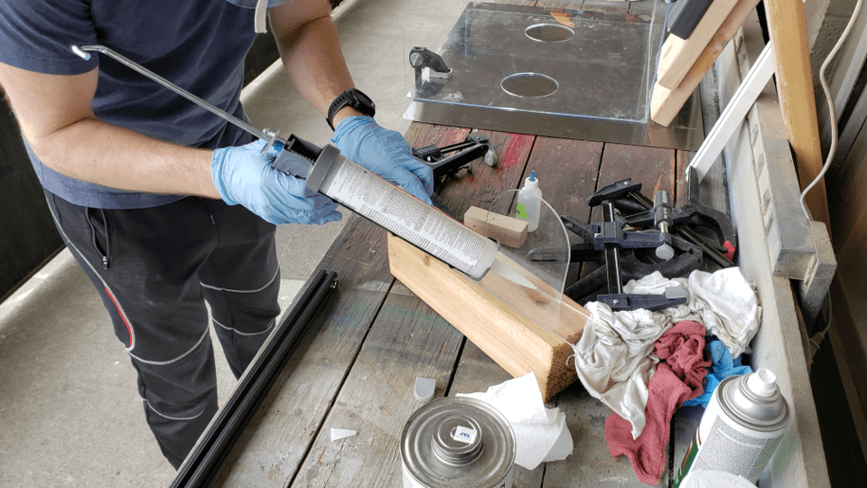
Image 8 – Practicing caulking on scrap pieces of acrylic.
After a bit of practice, we began caulking the actual box (Video 9).
Video 9 – Caulking the box seams.
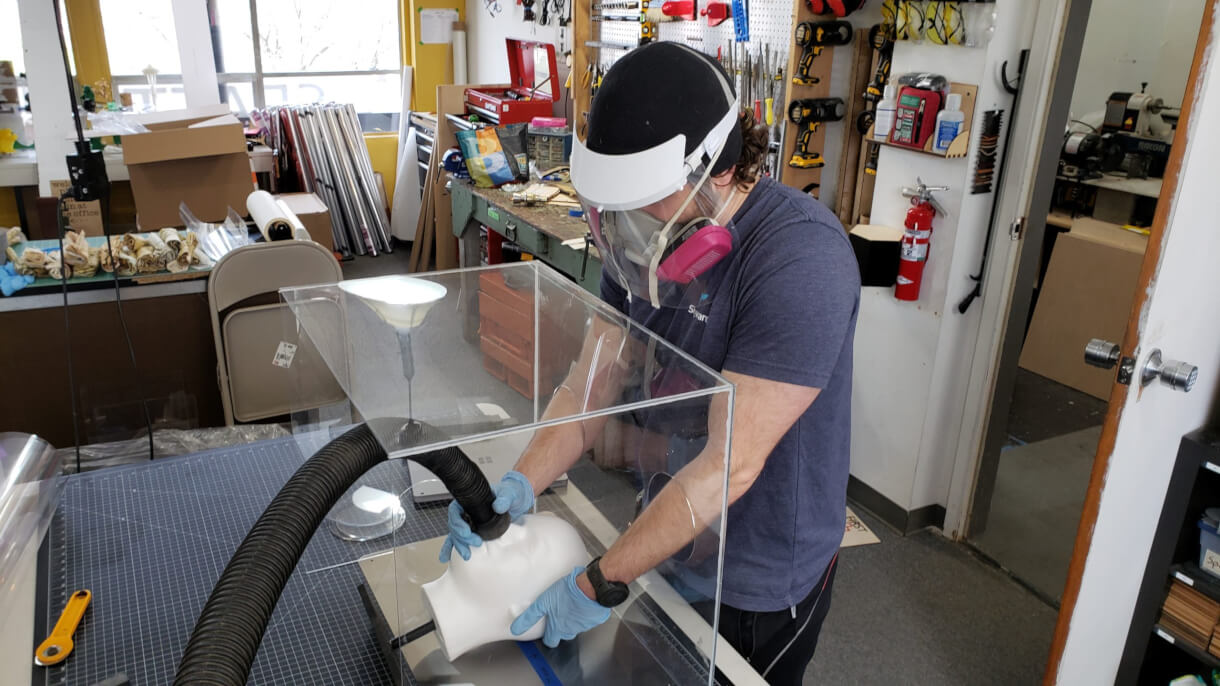
We let the caulking set for 24 hours, and then the box was ready for full scale testing (Image 10).

Image 10 – Testing the completed box.
All done (Image 11)!
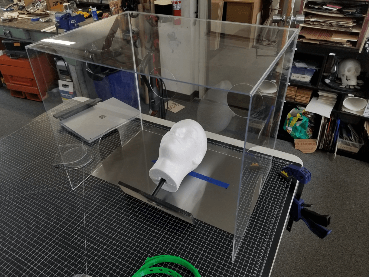
Image 11 – The completed box.
This box did NOT last long. It fell apart after a couple demos, so it was time to examine what we learned, and then move on to Version 2.
WHAT WE LEARNED
Throughout this process we certainly learned a few things so we wouldn’t repeat the same mistakes again. The box we produced is definitely usable but there are some improvements that can be made in areas of: 1) material choice, 2) joining, and 3) understanding underlying requirements.
1. Material Choice and Thickness
We settled on acrylic because it’s easy to laser cut, cheap, and widely available. It is, however, brittle. The top panel of the box (blue in Image 12) is quite large and spans a large distance while only being supported on three sides. That means that any impact or substantial weight placed on the top has the potential to deflect the acrylic to the point where it would simply snap the plastic.
A different material, like Plexiglass, would bend much more before breaking.
The thickness used, 0.118in, is likely as thin as we would go. A thicker plastic (perhaps 0.25in) would reduce the deformation when a load is applied, and would increase the adhesion contact area.
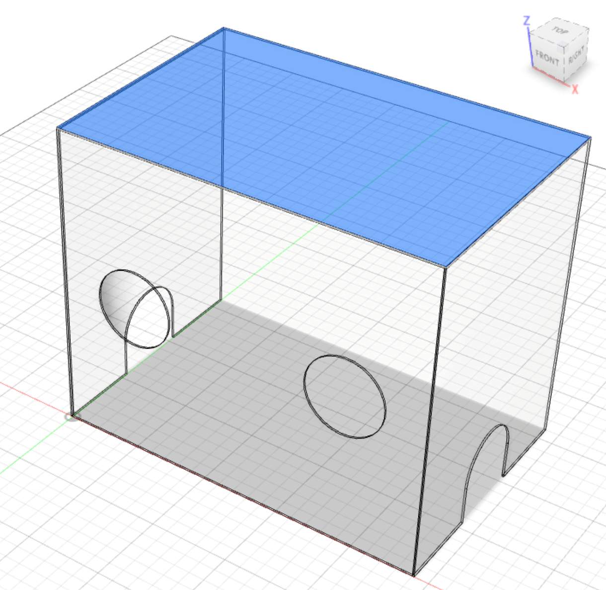
Image 12 – Showing the span of the top piece of acrylic (in blue).
2. Joining method and technique
a. Limited contact area
We didn’t plan for the effect of the angeled kerf caused by the laser. This led to a triangular edge shape (Image 13) which reduced the contact area for the acrylic cement. This would have been less of an issue if we had chosen a different type of adhesive than acrylic cement, perhaps one with more body so it doesn’t rely solely on the capillary action to fill the gap but instead could add material to the joint. The caulk certainly helped to offset this issue, but caulk wouldn’t be necessary with a more viscous adhesive.
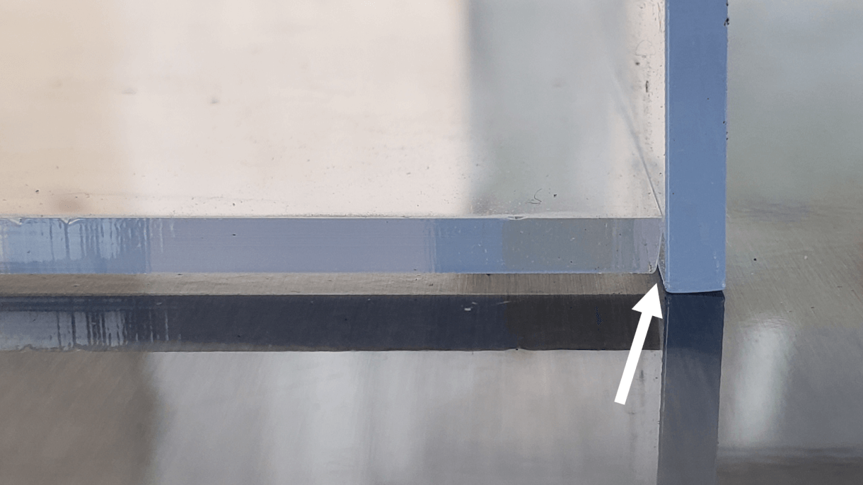
Image 13 – The arrow shows the angled cut edge of the acrylic and the gap between pieces.
B. Gluing on Planar Surfaces with Very Thin Glue
Another unintended consequence of very thin glue was that it wicked between the acrylic and the support panels below it which melted some of the face plate and caused cosmetic damage (white circles in Image 14).
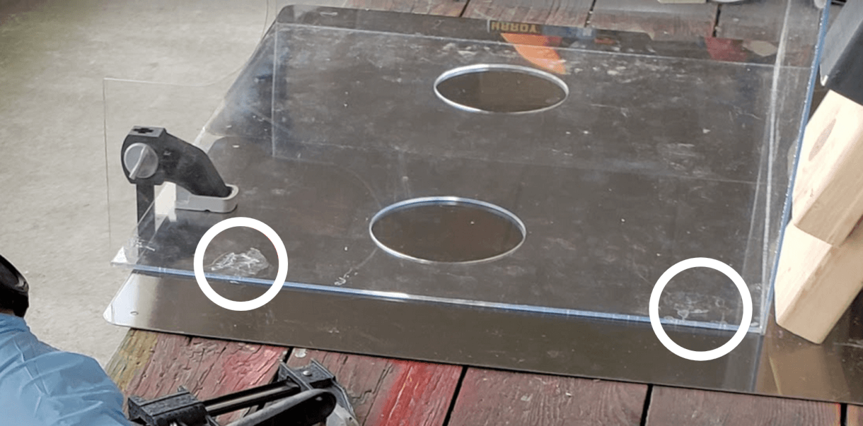
Image 14 – White circles show the cosmetic damage caused by acrylic cement.
C. Joining Method
True to the original design, we attached the panels with flat joinery at the edges. However, this is a labor intensive method that requires a relatively high level of precision, both in manufacturing the constituent panels and during assembly. Using finger joints instead (as in Image 15), where notches are cut and fit together, would vastly increase the joining surface area and markedly increase the strength of the overall design.
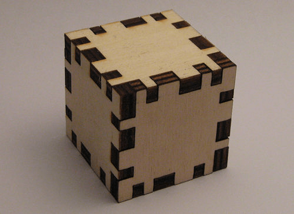
Image 15 – Example of finger joinery. Image courtesy of Instructables.com.
There are also designs where the edges stick out past the joining surface which are incredibly easy to assembly and offers a non-permanent attachment method if desired (Image 16). One can be seen here.
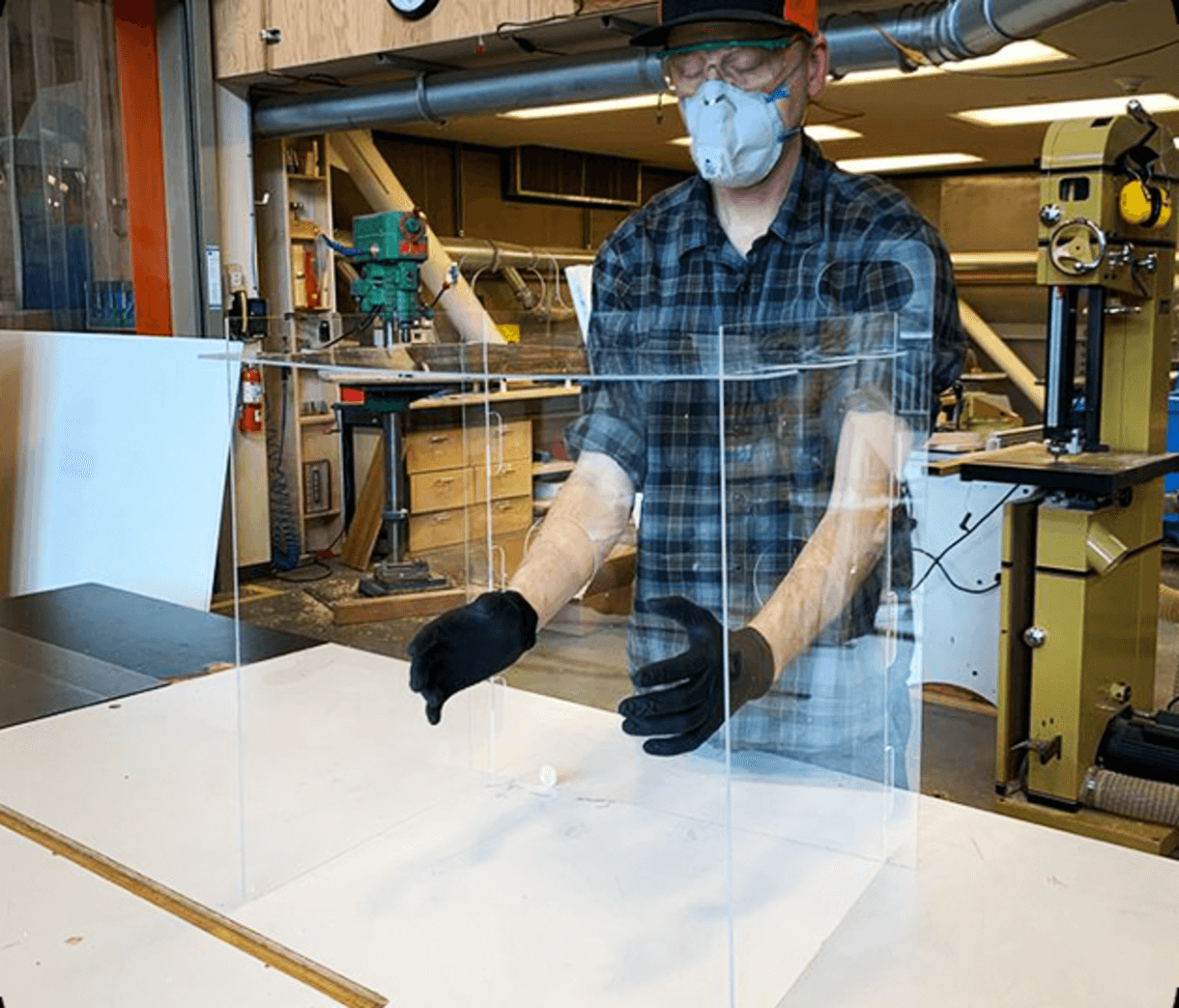
Image 16 – Example of aerosol box where edges extend beyond the joining surfaces. Image courtesy of SomethingLabs.org.
3. Underlying requirements
Ultimately it would be beneficial to directly talk to doctors using this box to learn what the true underlying requirements are. Obviously medical professionals are short on time these days, but it would have helped to learn as much as possible before selecting materials and attachment styles. For example, there are some types of plastics that can survive the autoclave process if that sterilization method is preferred to wiping down with alcohol.
We can also add small things for increased comfort. For example, if the doctor is resting their arms in the cut out holes for a long time, those should be lined with a removable foam.
VERSION 2
Supplies
- 0.25″ thick acrylic (72″ x 36″ sheet)
- Weld-on 16 acrylic plastic cement
- laser cutter
- clamps
- 2×4″ scraps of wood (to aid with clamping)
Production
After Version 1 fell apart, we made the following significant changes:
- doubled the acrylic thickness (0.25″)
- redesigned the box to have tried-and true finger joints for the box seams
- used an adhesive with more body (the goopy Weld-On 16, vs. the thin, watery Weld-On 3)
- filed down the corners so they aren’t so sharp (Image 17a vs Image 17b)
1. Material thickness
Increasing material thickness meant there was more surface area touching at the joints, creating a stronger box. We increased material thickness from 0.116″ to 0.25″ (Image 18)
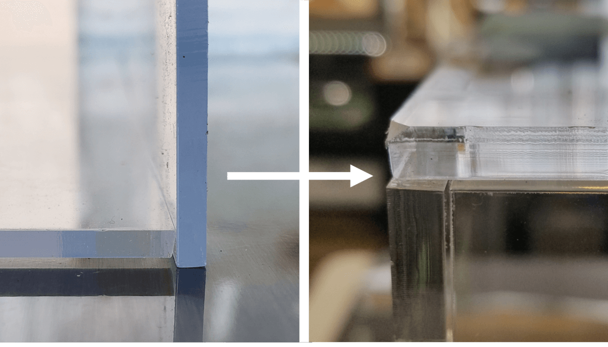
Image 18 – Comparison of Version 1 acrylic thickness (on the left – 0.116″) and Version 2 acrylic thickness (on the right – 0.25″)
2. Type of Joinery
In Version 1, we used a simple flat seem, simply gluing one straight edge against another straight edge. For Version 2, we used much more robust finger joints which increase the surface area contact between the two pieces that are being joined (Image 19). The .dxf file we used for the laser cutter is here.
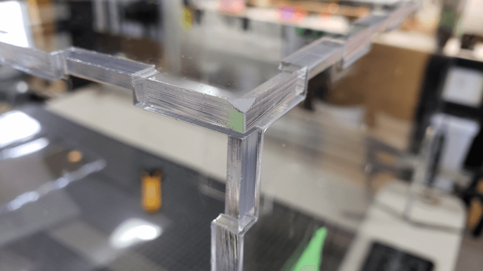
Image 19 – Finger joints connected the box.
We assembled the entire box using this type of joinery (Image 20).
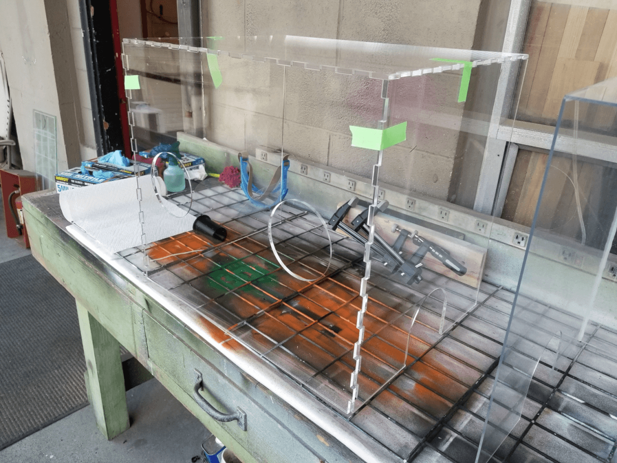
Image 20 – Finger joinery used to assemble entire box.
3. Adhesive
For Version 1, we used used Weld-On 3, a watery acrylic plastic cement. However, it didn’t create an air-tight seal at the joints, so we also used silicone caulking to create a tight seal. Ultimately, neither of these adhesives were strong enough and the box fell apart quickly.
For Version 2, we used Weld-On 16, which is significantly more viscous (or, to use the scientific term “goopy”). This created a very strong bond between pieces of acrylic AND also made the joints air-tight.
4. Filing down corners
A great thing about laser cutters is their precision cutting of acrylic. A bad thing about laser cutters is their precision cutting of acrylic, which can lead to VERY sharp corners. On Version 1, we noticed that the corners of the box and the edges of the arm holes were pretty sharp and uncomfortable to use. For Version 2, we wanted to fix that, so out came the file (Image 21).
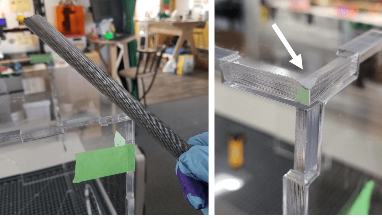
Image 21 – We used a rough-cut file to file down the box corners.
We used the file on every edge and corner (Image 22).
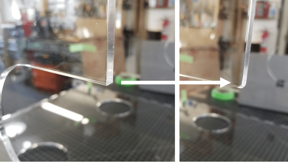
Image 22 – Before and after filing a corner.
Testing
No prototype would be complete without a test, and in this case, the best test is a sneeze. It started with a simple statement: “Hey let’s take a minute to demo a fake sneeze to show how it works.” 20 minutes later… (Video 23).
Video 23: Ultra-slow-mo demo of a “sneeze”. We filmed from outside the intubation shield.
Confirmed. Acrylic does stop water droplets. (Image 24).
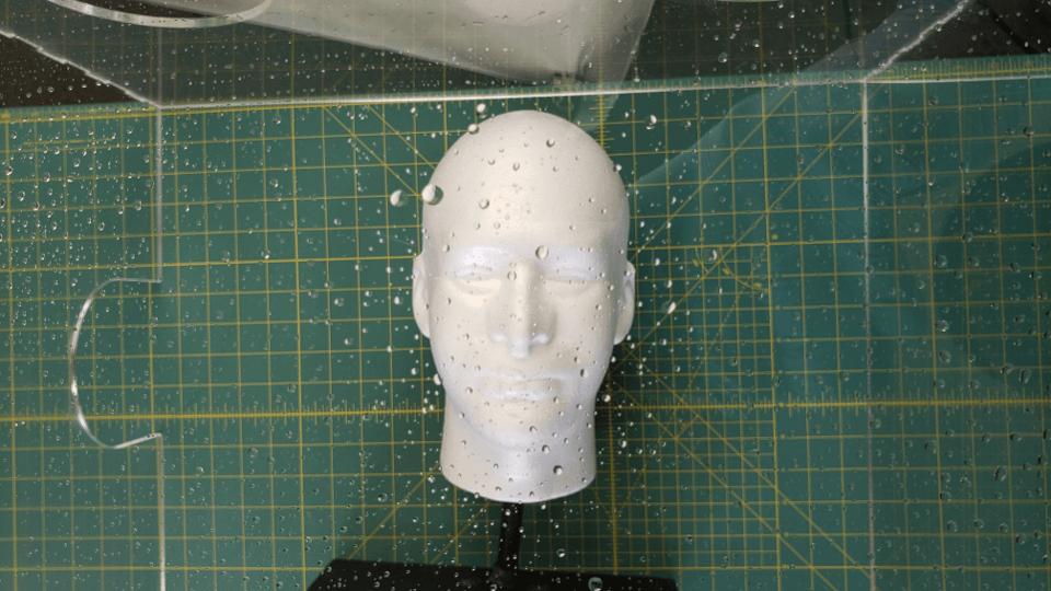
Image 24 – A blocked “sneeze”.
Stephen Ou, who works at the UW Northwest Campus in Emergency, came by to pick up the box and show us how it was used (Image 25), and gave us valuable feedback, and the top priorities for the design: foldable, easy to sanitize.
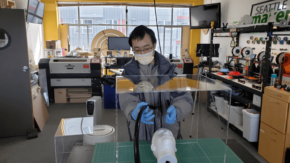
Image 25 – Stephen Ou demoing Version 2.
Next Steps
For future models we are looking to use polycarbonate and hardware connections, which will increase strength, decrease production time, and minimize the surfaces to sanitize, while allowing it to be dismantled and stored flat when not in use. We are working with local CNC companies, and artists at Equinox to develop this design.
We funded 80% of this project with your contributions. Thank you for your donations! Also a huge thanks to Jonathan Lenoff for designing, cutting, and assembling (and re-designing, re-cutting, and re-assembling) the box.